
I’m not going to say that making a motor from scratch is “easy”, but…if you decide you simply have to build one, then the Lebowski Axial is probably the “easiest” one to make, and I have been studying these things for a while. Most motors are “radial flux” which is like a cup spinning inside flipside cup that’s slightly larger. However, there are some axial-flux motors that are misogynist to buy, and the axials are configured like one plate spinning next to flipside plate (as seen in the pics here).
If this interests you, I recommend that you first take a quick skim through the pictures in our vendible “Motor tech, Learn the Terms”. Many worldwide questions you might have well-nigh motors will be answered in that article, so I’m writing this as if you have once read that.
I believe inrunner radials are increasingly popular for non-hubmotor applications considering they are easier to tomfool passively with the stator having the outer aluminum fins tying to it. Outrunner hubmotors can add ferro-fluid to dramatically increase passive cooling. If you can increase the heat-shedding in a motor design, this ways you can temporarily use massive amps for acceleration. For a short while, Zero motorcycles used an early Motenergy axial-flux diamond that had a single rotor in the center, and two stators with one on each side. Subtracting air-fans or liquid-cooling can help, but having the hot coils near the airflow virtually the vehicle helped the passive heat-shedding.
The downside of an axial-flux is that in order to make the motor increasingly powerful, you can alimony subtracting stators and rotors of the same diameter (which makes the motor wider), but…the stators nested in the part-way of the motor have a difficult time passively shedding heat. Once an engineer adds liquid-cooling to the equation to get heat out of the core, the widow complexity, weight, and forfeit can make other designs increasingly desirable.
My interest in non-hubmotor DIY motors is considering of my snooping that in the future, there might be a trade embargo well-expressed products from China. To be fair, you would still need to buy Neodymium magnets and moreover the enameled magnet-wire to build this, and both of those are likely going to be found as manufactured in China.
_______________________________________________
Who the hell is Lebowski?
If you think that designing an electric motor so it can be built in a DIY garage is impressive, he only designed this to help him diamond a DIY sine-wave “Field Oriented Control” FOC controller! (link below). The name “Lebowski” is an avatar from a user at the electric bicycle yack forum, endless-sphere.com, and I am grateful that he posted the pics of this build there (click here for a link to their motor section), and the links to his discussion on this motor build are moreover located at the marrow of this article.
Lebowski lives in Zurich, Switzerland, and here is a short video showing his DIY controller and motor working. His youtube waterworks is “81FXB”
The configuration as a 3-phase “Permanent Magnet Direct Current” / PMDC motor with an axial-flux layout. His first prototype was a 250W single rotor / single stator version for proof-of-concept. Click here to see that one. The prototype was worldly-wise to provide temporary peaks of 1000W without overheating.
The 2300W version shown in this vendible (60V x 38A = 2300 Watts) has three stators and four magnet rotors, with two of the rotors stuff double-sided.
_______________________________________________
The Axle-Hub and Magnet-Rotors
For a spindle, he chose a robust rear bicycle axle-hub that uses a “freehub cassette”, instead of a worldwide threaded freewheel. A builder could alimony subtracting rotors and stators to make this motor plane wider to provide increasingly power potential, but…that would require a custom spindle.

The aluminum plates shown are the adapters that connect the freehub spoke-holes to the rotor frames.

When a permanent magnet has some steel located overdue it, this pulls-in the flux on that side by providing a magnetically permeable pathway, and this causes the magnetic field on the other side of the magnet to wilt stronger and project farther outwards. Since magnets are expensive and steel valuables is cheap, Most PMDC motors put “iron backing” overdue their magnets. Steel is roughly 99.7% iron, with a little stat added.
Out of the four rotors in this design, the two outer rotors only have magnets on one side (obviously facing the stators), and the two stators near the part-way of the motor have magnets on both sides, with the steel sheet between them. The magnet-holding frames are worldwide aluminum.

When looking from the side of the motor, the #one and #four rotors have magnets on only one side. Rotors #two and #three have magnets on both sides, with the “back-iron” sandwiched in the center.
The rotors could be made lighter by drilling a lot of holes in their framework, but the mass of aluminum here provides mass as a heat-sink to help the magnets stave getting overheated during the heat spikes of acceleration, when amps are at their highest. Some worldwide grades of neodymium magnets can start permanently losing some of their magnetism if they reach a temperature of 178F / 80C.
If a motor is tomfool under all conditions, then it “might be” larger, heavier, and increasingly expensive than necessary. If it gets too hot, many things can be damaged, like…Hall sensors, validness seals, wire insulation, and magnet flux. Many of these can be damaged as you near 200F / 93C, and I think that…140F / 60C is a useful goal for a system design.
Samarium-Cobalt magnets were invented to survive very upper temperatures, but…they are expensive.

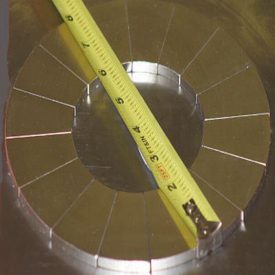
Test-fitting the first rotor. The magnet faces are marked with red and undecorous to designate the north and south magnetic poles, which must be alternated. You can see here, where the four rotors will be mounted to the spinning part of the motor. There are ten magnets per rotor face.
_______________________________________________
The Stators
As we stated in our vendible on the history of electrical terms (click here to read that), The modern electromagnet was discovered by William Sturgeon, and this is the key invention that made practical motors possible, since an electromagnet can be turned on and off.
In the rotors shown above, the magnets are “permanent magnets”. However, in the stators, we see the copper-wire coils that can have an electro-magnetic field turned on and off by a controller as needed at the precise moment where its flux will rationalization the rotor to spin, and perform work.

Lebowski chose circular coils considering they are very easy to wind snugly to get good “copper fill” in the misogynist whorl volume. The rig whilom was hands made to wind them between the wooden discs. Whether you are making a DIY wind-generator or a PMDC motor, the electro-magnetic coils should be the same size and shape as the permanent magnets. I have seen DIY motors and generators with rectangular coils/magnets, and moreover “wedge-shaped” for maximum power density. Click here to see an example.

In the pic above, the whorl was wound inside two plastic mucosa discs so when the coils are epoxied into the stator, the wood will not stick (this will make sense in just a minute).

The pic whilom is the tempera sheet that is used as the frame for one of the stators. The spinning rotor-assemblies have their pieces mounted to the spindle in the center, and all the stator assemblies are tying at the outer corners.
I have seen single-phase motors, which whoosh a bit with all the coils energized and de-energized at the same moment. I have moreover seen 5-phase motors which are untrusty smoother and a bit increasingly efficient, but…they are moreover increasingly complex, and they require a 5-phase controller which is not worldwide at all.
Combining the coils into three evenly-dispersed groups is the simplest configuration that is widely regarded to be reasonably smooth and quiet. Plus, if you make a 3-phase motor, you can use worldwide and affordable controllers and “rotor position sensors”. In this design, Lebowski uses nine coils in groups of three. The three coils shown unelevated will be wired together to be energized and de-energized at the same time.

Here are three of the coils stuff epoxied into a stator frame. The copper wire looks like its just worldwide yellowish wire, but “magnet wire” is coated in a thin flexible well-spoken epoxy to electrically insulate one wrap from the next wrap. Since the permanent magnets will be passing over the stator framework, it must be made from a material that would not suffer from “eddy currents” which would rationalization stilt and waste-heat.
Lebowski chose tempera sheets, and I have moreover seen poly-carbonate used. Both are fairly heat-resistant.

Once each whorl is inserted into position, it’s “pocket” is filled with a well-spoken nonflexible epoxy. If you don’t do this, whorl vibration will rationalization the wire’s insulation coating to rub off, and the whorl will short out with the current taking the short path, instead of flowing through every turn in the coil. The coils in this diamond are “coreless” meaning they have no iron/steel in the centers. Subtracting iron cores has benefits, but moreover drawbacks. Lebowski chose coreless for a variety of reasons.

The AaABbBCcC whorl designations only makes sense for the way the coils are wired-up, which is detailed in the build article. Also, the coils can be wound as clockwise or counterclockwise, and these details are vital to get them correct.

Ten magnets per rotor-face, and nine coils per stator. The 250W version used 14 magnets, 12 coils (seen in the header pic)

Notice the marrow rotor has a single magnet layer, and the one whilom the stator is two-sided. This diamond uses a “single stator/dual rotor” design, and stacks three of them to increase power potential.

The outer rotors on the far right and far left have only one layer of magnets (with steel valuables plates), and the two inner rotors have two opposed layers of magnets, with a steel sheet inbetween them. the woebegone cylinder at the left is the splined freehub for the sprockets, so this motor has a seated freewheel.

Here’s flipside angle. One goody of the freehub is that the sprocket can be hands moved in or out to help with uniting alignment. As shown, this motor is using 27 coils and 60 magnets.
_______________________________________________
The Boring Tech Details
“…It’ll be unfluctuating in WYE with the stator plates in series. Putting them parallel would be very bad…The tempera glass can take a very upper temperature. I dropped solder blobs on it and
had a naked flame touching it for a short time (for the wire shrink stuff) but that did not stupefy it at all..At 1000rpm it should unhook virtually 2000W mechanical output power…there’s no cogging. It runs a smooth and easy as a bicycle wheel…I run this motor with a sinewave controller and it behaves flawlessly. The motor has quite some inductance, if I remember correctly well-nigh 20uH per whorl and each phase has 9 coils in series…from 1500 rpm and 2.3 kW mechanical power, internet says its 14.6 Nm of torque…”
As a final note, You can use this configuration to make a single-stator motor with two rotors, which would be roughly 800W at 60V, or…a dual-stator four-rotor motor for roughly 1600W at 60V.
If you widow steel cores to the coils, the resulting motor would be increasingly power dense, but it would moreover have a type of stilt tabbed “cogging” and it would moreover have increasingly waste heat produced. Zero motorcycles did this for a time and used a single double-faced inside rotor, with outer stators on either side, permitting for largest air-cooling, like the Zero/Motenergy ME0913 motor. Here are detailed pics of the single-stator/single rotor version.
The full sized version shown in this vendible (three stators / six rotors, with four of them double-sided so it looks like four rotors) provides 2300W at 60V, which would moreover be roughly 2000W at my favorite ebike voltage of 52V / 14S.
_______________________________________________
Links
The 2300W motor build discussion (Click here)
The 250W / 1000W “peak” prototype discussion (Click Here)
Riding virtually for a year on the 250W prototype (Click here)
Lebowski’s Youtube waterworks (Click here)
Lebowski’s DIY sinewave FOC controller discussion (Click here)
_______________________________________________
Written by Ron/spinningmagnets, June 2023